Monday, April 8, 2013

Building a VMware Virtual Machine Template - Walkthrough Guide

**** Updated 06-12-2013 **** Spelling corrections, updates to notes and included OS video card update information.

There are quite a few posts already on building a VM template but I found that I was having to reference a several blog posts in order to get the complete picture. So I'm finally getting around to writing my own for future reference.

I'll list some great links to other VM Template guides at the end of the post.

  • Create a new VM with the required specifications.
    • Disk
    • CPU - Make the default use CPUs not Cores
    • RAM
    • NIC - VMXNET3
    • SCSI0 - LSI Logic SAS for Windows 2008
    • Floppy - Remove
    • OS - Make sure to select the correct OS
  • Build a standard for the template name to cover different OS versions and editions for example;
    • W2K8R2SP1ENTx64 - Windows 2008 R2 Service Pack 1 Enterprise 64bit
    • W2K3SP2STDx32 - Windows 2003 Service Pack 2 Standard 32bit
    • RHEL61x64 - Red Hat Enterprise Linux 6.1 64bit
  • Install the OS inside the VM (typically from CD ISO)
    • Choose a default Administrator username and password
    • Set time zone
    • Set regional options
    • Set language packs
    • Set keyboard layout
  • Upgrade VM hardware version to the latest level available
  • Modify VM settings
    • Disable VM Logging
    • Set CD/DVD to 'Client Device'
    • NIC - Select default build VLAN/Portgroup
    • Video Memory - For one monitor @ 1024x768 use 3MB
    • Set description of the template within the Notes section
  • BIOS Settings
    • Disable serial ports
    • Disable parallel ports
    • Set HDD as primary boot device
    • Disable floppy disk drives
  • Install VMware Tools - Choose custom install
    • Unselect vShield Drivers
    • Unselect Shared Folders
    • Unselect Virtual Printing
    • Unselect Wise Multimedia Support
  • Update video card driver to WDDM driver (kb.vmware.com/kb/2004145‎)
  • Anti-Virus client install - Agentless is preferred if that is available
  • Backup client install - Agentless is preferred if that is available
  • Set VM name within the OS to match the template name
  • Activate OS - Microsoft KMS if available
  • Enable Remote Desktop
  • Create folders on C:\ partition
    • C:\Temp
    • C:\Scripts
    • C:\Source
    • C:\Tools
    • C:\BGInfo
  • Configure BGInfo application
    • Create a shortcut with the following syntax; C:\BGInfo\Bginfo.exe "C:\BGInfo\BGinfo_Win2K8.bgi" /SILENT /TIMER:0 /NOLICPROMPT
    • For Windows 2008 put the shortcut in: C:\ProgramData\Microsoft\Windows\Start Menu\Programs\Startup
    • For Windows 2003 put the shortcut in: C:\Documents and Settings\All Users\Start Menu\Programs\Startup
  • Install Windows Updates
  • Install Windows Features but do not install the following options by default;
    • Microsoft .Net Framework
    • Silverlight
    • IE Compatibility
    • Best Practices Analyzer
  • Set Power Plan to High Performance
  • Set Turn off the display to Never
  • Set Put the computer to sleep to Never
  • Firewall - Set on or off depending on your organization policies and practices
  • Disable UAC
  • Set screen resolution to 1024x768
  • Purge Temporary Folders;
    • C:\Windows\Temp
    • C:\RECYCLED
    • C:\Windows\SOFTWAREDISTRIBUTION\DOWNLOADS
    • C:\Windows\$directory$
    • C:\Users\Administrator\AppData\Local\Temp
  • Release IP address of server (Set to DHCP)
  • Shutdown VM
  • Convert VM to template
Notes:
The CD-ROM drive will be set as D: drive by default. I always change this to Z: drive, but this cannot be part of the template. There are smarter ways to do this, like scripts that run post deployment.

Once every couple of months we need to convert this template back to a VM, power it on and then patch it up to the latest version. Then redo the steps from Purging Temporary Folders onwards.


Comprehensive guide and walk through on building VM Templates;
List of Sysprep files required for various operating system customization's;
Tuesday, February 19, 2013

ESXi Custom Image Build Walkthrough

The following post is a detailed walkthrough on the process of creating a customized ESXi image. This would be used when building a vSphere environment with servers that must have components upgraded for functionality or support.

For this walkthrough I will be using Cisco UCS blade and rack servers. Also in use is Cisco VM-FEX technology which leverages the Nexus 1000v Virtual Ethernet Module (VEM) so this component will need to be installed along with the drivers for Cisco's VIC1280 Converged Network Adapter (CNA).

You may wonder why it is that I'm using a customised image based off VMwares standard ESXi source instead of the Vendor supplied ESXi image. The answer is quite simple; on every project I've ever worked on the Vendor supplied installation media is always several versions behind. At the time of writing this post Cisco only has a Cisco branded ESXi image up to version 5.0 and what I need right now is 5.1. In my experience it is always better to take the VMware branded image and add the components required.

The first step is to download the ESXi ZIP bundle and the driver bundles for the Nexus 1000v and the CNA card, and then store them in a temporary location. Specifically the files I'm working with for this post are;
  • ESXi510-201210001.zip
  • Nexus1000v.4.2.1.SV2.1.1.zip
  • enic_driver_2.1.2.22-564611.zip
  • fnic_driver_1.5.0.8-758653.zip

Now we need to pull the offline bundles out of the driver packages. We are looking for a zip file inside the zip file with the following folders/files in the root;
  • vib20
  • index.xml
  • metadata.zip
  • vendor-index.xml
Once we find the files, copy them to the temporary location. They must stay as ZIP files so that the PowerCLI cmdlets can interact with them. In this situation the offline bundles are;
  • VEM510-20121019150119-BG-release.zip
  • enic_driver_2.1.2.22-offline_bundle-564611.zip
  • fnic_driver_1.5.0.8-offline_bundle-758653.zip

Now it is time to launch PowerCLI and create the image. It is important to note that all data within this session will disappear once the PowerCLI window is closed. Before closing this window at the end of the walkthrough make sure to save both the ISO and ZIP files for easy re-import next time walking through this process.


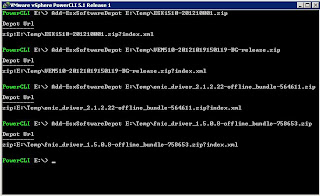
Add the ESXi image and driver bundles to the Software Depot repository.
  • Add-EsxSoftwareDepot E:\Temp\ESXi510-201210001.zip
  • Add-EsxSoftwareDepot E:\Temp\VEM510-20121019150119-BG-release.zip
  • Add-EsxSoftwareDepot E:\Temp\enic_driver_2.1.2.22-offline_bundle-564611.zip
  • Add-EsxSoftwareDepot E:\Temp\fnic_driver_1.5.0.8-offline_bundle-758653.zip


List all current ESXi image profiles, make a new image profile by copying the existing standard image and then list the components that are going to be added. The asterisk (*) can be used as a wildcard in PowerCLI.
  • Get-EsxImageProfile | FT Name, Vendor
  • New-EsxImageProfile -CloneProfile ESXi-5.1.0-20121004001-s* -Name ESXi-5.1.0-b838463 -Vendor VRIF
  • Get-EsxSoftwarePackage -Vendor Cisco


Add each of the required packages to the newly created image.
  • Add-EsxSoftwarePackage -ImageProfile ESXi-5.1.0-b838463 cisco-vem-v150-esx
  • Add-EsxSoftwarePackage -ImageProfile ESXi-5.1.0-b838463 net-enic
  • Add-EsxSoftwarePackage -ImageProfile ESXi-5.1.0-b838463 scsi-fnic


Compare the source profile to the newly created profile and confirm that the extra components have been added.
  • Compare-EsxImageProfile -ComparisonProfile ESXi-5.1.0-b8* -Reference ESXi-5.1.0-20121004001-s*


Export the image to be used as an ISO and ZIP bundle. The ZIP bundle is required for easy re-import into a PowerCLI session.
  • Export-EsxImageProfile -ImageProfile ESXi-5.1.0-b8* -ExportToIso -FilePath E:\Temp\ESXi-5.1.0-b838463.iso
  • Export-EsxImageProfile -ImageProfile ESXi-5.1.0-b8* -ExportToBundle -FilePath E:\Temp\ESXi-5.1.0-b838463.zip


Now the ISO file can be used as a normal ESXi build disc. Attach it to your host and build the OS.

The ZIP bundle can be used to re-import the Image back into PowerCLI for editing and updating.

This process is just one of many ways to get extra drivers installed into ESXi. The reason I like this method is that you only need to do it once and then roll out the image to the hosts.


Tuesday, September 25, 2012

vSphere 5 Host Network Design - 10GbE & 1Gb Hybrid Ent+ Design


This design comes from multiple requests for a 10GbE and 1Gb hybrid environment. Many organizations want to make use of the investments they have made into 1Gb infrastructure for as long as they can and therefore this has been a common request for a design.

This design makes use of Enterprise Plus licenses to enable bandwidth control on the 10GbE network. If you do not have Ent+ then consider pinning VM Network to vmnic4 and Storage to vmnic5 using a single portgroup per traffic type.

Please note that this and all my other designs should be considered starting point for your own specific design. There is no one-size-fits-all configuration, only good practises to minimise risk, maximise throughput and to get the best return on investment.

It is assumed that each host has two 10GB NICs provided by a single PCI-x Dual Port expansion card and four 1Gb uplinks provided by a single quad port card. Whilst this isn't the best configuration for redundancy it does represent what a lot of organizations are currently doing. So whilst I like to build optimal configurations, that's pointless when it never happens because of the budget.

Management and vMotion are done from a single vSS using four uplinks going to two seperate switches. However this design could be made slightly less complex by seperating out Management and vMotion onto their own standard switches. What we gain in this design is 2Gbps throughput for both vMotion and Management (think cold migrations) on a single switch. It is important to note that each of the Management vmkernels should be going to seperate physical switches, ditto with the vMotion uplinks. This will ensure that traffic is balanced across the physical network.

It isn't shown in the diagram and I probably don't need to mention it, but somewhere in the back end the 10GbE and 1Gb networks will need to be able to communicate with each other.
VM Networking, iSCSI and Fault Tolerance (FT not shown in this design but could be inlcuded by adding the FT vmkernel ports onto dvSwitch1) traffic is assigned to a single distributed virtual switch. Only VM Networking makes use of Load Based Teaming (LBT) in conjunction with Network IO Control (NIOC) and Storage IO Control (SIOC). A good writeup on how to configure NIOC shares can be found on the VMware Networking Blog. LBT is a teaming policy only available when using a virtual Distributed Switch (vDS). I have used two iSCSI vmkernels and configured them using a specific failover order. Storage does make use of NIOC and SIOC but does not use LBT, VM Networking traffic is aware of what iSCSI is doing and will allow for it without issue.

LACP is not used as it wouldn't be a good design choice for this configuration. LACP has had some major improvements with vSphere 5.1, but for now I am still not including it in my designs. A valid use case for LACP could be made when using the Nexus 1000V as LBT is not available for this type of switch.

In order to gain the performance increase of Jumbo Frames for the storage layer all networking components will need to have Jumbo Frames enabled. The requires end-to-end configuration from the hosts through the network and to the storage arrays. There is definitely a performance increase by incorporating Jumbo Frames and this is outlined in the following blog post. It is important to note that enabling Jumbo Frames on the single switch will allow all traffic to transmitt at 9000MTU. This means that FT and Storage will all use Jumbo Frames. VMs will not use Jumbo Frames unless this feature is enabled on the network adapter inside the OS of the VM.

Trunking needs to be configured on the 1Gb physical switches to allow for Management and vMotion traffic. Trunking also needs to be configured on the 10GbE physical switches to allow FT, VM Networking and Storage traffic. Trunking at the physical switch will enable the definition of multiple allowable VLANs at the virtual switch layer.

If you need to present iSCSI straight up to a VM then this can be enabled by adding the Storage VLAN to the list of VLANs that can be accessed within the VM Network portgroup. I try my best to avoid doing this as it opens up the Storage layer to attack, but sometimes this is a requirement for some organizations.

When running Cisco equipment there is the potential to use the Rapid Spanning Tree Protocol (802.1w) standard. This means there is no requirement to configure trunk ports with Portfast or disable STP as the physical switches will automatically identify these functions correctly. If running any other type of equipment the safest option would probably be to disable STP and enable Portfast on each trunk port, but please refer to the switch manufacturer manual for confirmation.
Since this design makes use of standard virtual switches it is acceptable to have vCenter as a VM on the same hardware that is being managed. However it is always a good practise to have a seperate management cluster if that option is available.

*** Updates ***
5th of November 2012 - Fixed minor issues with the iSCSI port groups.

Sunday, April 29, 2012

vSphere 5 Host Network Design - 10GbE vDS Design


This design represents the highest performance, most redundant and also most costly option for a vSphere 5 environment. It is entirely feasible to lose three out of the four uplink paths and still be running without interruption and most likely with no performance impact either. When looking for a bullet proof and highly scalable configuration within the data centre then this would be a great way to go.

The physical switch configuration might be slightly confusing to look out without explanation. Essentially what we have here are four Nexus 2000 series switches that are uplinked into two Nexus 5000 series switches. The green uplink ports in the design show that each 2K expansion switch has 40GbE of uplink capacity to the 5Ks. Network layer 3 routing daughter cards are installed within the Nexus 5Ks and now traffic can be routed within the switched environment instead of going out to an external router. In other words traffic from a host will travel up through a 2K, hit a 5K and then come back down where required. It isn't apparent from the design picture, but Keep-Alive traffic is run between the console ports of the two 5K switches.

It is assumed that each host has four 10GB NICs provided by 2 x PCI-x Dual Port expansion cards. All NICs are assigned to a single virtual standard switch and bandwidth control is performed using Load Based Teaming (LBT) in conjunction with Network IO Control (NIOC) and Storage IO Control (SIOC). A good writeup on how to configure NIOC shares can be found on the VMware Networking Blog and whilst this information is specific for 2 x 10GbE uplinks it also holds true when using four 10GbE connections. LBT is a teaming policy only available when using a virtual Distributed Switch (vDS).

LACP is not used as it wouldn't be a good design choice for this configuration. There are very few implementations where LACP/Etherchannel would be valid. For a comprehensive writeup on the reasons why please check out this blog post. A valid use case for LACP could be made when using the Nexus 1000V as LBT is not available for this type of switch.

In order to gain the performance increase of Jumbo Frames for the storage layer all networking components will need to have Jumbo Frames enabled. The requires end-to-end configuration from the hosts through the network and to the storage arrays. There is definitely a performance increase by incorporating Jumbo Frames and this is outlined in the following blog post. It is important to note that enabling Jumbo Frames on the single switch will allow all traffic to transmitt at 9000MTU. This means that Management, vMotion, FT and Storage will all use Jumbo Frames. VMs will not use Jumbo Frames unless this feature is enabled on the network adapter inside the OS of the VM.

Trunking needs to be configured on all physical switch to ESXi host uplinks to allow all VLAN traffic including; Management, vMotion, FT, VM Networking and Storage. Trunking at the physical switch will enable the definition of multiple allowable VLANs at the virtual switch layer. All VLANs used must be able to traverse all uplinks simultaneously.

When running Cisco equipment there is the potential to use the Rapid Spanning Tree Protocol (802.1w) standard. This means there is no requirement to configure trunk ports with Portfast or disable STP as the physical switches will automatically identify these functions correctly. If running any other type of equipment the safest option would probably be to disable STP and enable Portfast on each trunk port, but please refer to the switch manufacturer manual for confirmation.

Running vCenter and the vCenter database on the same clusters that are managed is going to create a dangerous circular dependency. Therefore it is strongly recommended to make sure that the environment has a management cluster dedicated for vCenter and high level VMs, where the management cluster uses virtual standard switches (vSS). One alternative to a dedicated management cluster would be to run vCenter and it's database as physical servers outside of vSphere.


*** Updates ***

05/05/2012 - Minor update to Jumbo Frames paragraph. Thanks to Eric Singer for his observations.

07/05/2012 - Moved diagram to top of article so that visitors wanting to reference design do not need to scroll down the article to view the diagram. Fixed IP address and VMkernel typos.


Thursday, April 26, 2012

vSphere 5 Host Network Design - 10GbE vSS Design


Going forward my 10GbE designs will be doing more to answer questions around physical network setup and configuration. Therefore you will see more detail in the diagram then I normally give, especially in regards to how the physical switches are uplinked and interconnected. I had some network design input from Cisco engineers on this to ensure that redundancy and throughput are not compromised once vSphere traffic gets onto the physical switches.

There were many discussions around the use of Load Based Teaming and Etherchannel, neither of which is used in the following design. LBT is not used because licensing does not allow for it. For more information on LBT please check out this link.
LACP is not used as it would not be good design practise. There are very few implementations where LACP/Etherchannel would be valid. For a comprehensive writeup on the reasons why please check out this link.

The following design is based around a segmented 10GbE networking infrastructure where multiple physical switches are interconnected using high speed links. All traffic is segmented with VLAN tagging for logical network separation.

It is assumed that each host has four 10GB NICs provided by 2 x PCI-x Dual Port expansion cards. All NICs are assigned to a single virtual standard switch and traffic segregation is performed by pinning each VMkernel to a specific uplink. This is where design for 10GbE diverges from standard design in 1GB configurations. Typically for 1GB setup you would need at least two virtual switches or three when using iSCSI storage; switch1 for Management and vMotion, switch2 for VMs and switch3 for storage.

In order to gain the performance increase of Jumbo Frames for the storage layer all networking components will need to have Jumbo Frames enabled end-to-end from the hosts through the network and to the storage arrays. There is definitely a performance increase by incorporating Jumbo Frames and this is outlined in the following link. It is important to note that enabling Jumbo Frames on the single switch will allow all traffic to transmitt at 9000MTU. This means that Management, vMotion, FT and Storage will all use Jumbo Frames. VMs will not use Jumbo Frames unless this feature is enabled on the network adapter inside the OS of the VM.

Trunking needs to be configured on all uplinks where all ports on the physical switch allow all VLANs through. Trunking at the physical switch will enable the definition of multiple allowable VLANs at the virtual switch layer. It is important to note that the colours used in the diagram show how traffic will flow under normal circumstances. However all VLANs need to be able to use all uplinks in the event of a NIC failure.

If you are running Cisco equipment then you might be able to use the Rapid Spanning Tree Protocol (802.1w) standard. This means that you do not need to configure trunk ports with Portfast as the physical switches will automatically identify this port correctly. If running any other type of equipment the safest option would probably be to disable STP and enable Portfast on each trunk port, but please refer to your manufacturer manual.

Running vCenter and the vCenter database on the same hosts that it manages is not a problem in this design. So you do not need to run a Management cluster but I would say that it is usually a good design decision to do so. If you built this solution and then upgraded to Ent+ and started using virtual distributed switches then a Management cluster would be required.

This design is based around scenarios where Enterprise Plus licensing and network based bandwidth limiting/control is not available. Because SIOC and NIOC are not available in this design there is no way to guarantee bandwidth for particular traffic types. vMotion in vSphere 5 would be quite happy to consume 8Gb of an uplink and in situations where other traffic is running on that uplink it would be constricted by vMotion.


*** Updates ***

05/05/2012 - Minor update to Jumbo Frames paragraph. Thanks to Eric Singer for his observations.